CHC Navigation delivers precision geospatial solutions with advanced mapping systems, unmanned platforms, and GNSS+INS+LiDAR technology for spatial data capture.
CHC Navigation offers advanced GPS/GNSS machine control systems for excavators, dozers, graders, and compactors. Improve accuracy, cut costs, and complete construction projects faster with reliable global support.
CHC Navigation delivers high-precision GNSS + INS navigation systems for autonomous vehicle, automotive, robotics, mining, marine, and industrial applications.
We offer tractor guidance and auto-steering systems for farms of any size, powered by GPS farming technologies. Improve your precision agriculture practices with smart agriculture solutions starting today.
Ask a roomful of surveyors, drone operators, autonomous vehicle engineers, and BIM consultants what LiDAR is, and you will get five different correct answers. The technology has spread across industries fast enough that the word has become a catch-all, used for everything from a backpack scanner mapping a heritage building to the obstacle sensor on a self-driving truck. Underneath the variety is one shared physical principle, and a small set of design choices that explain why one LiDAR is right for one job and wrong for another. This guide walks through what LiDAR is, how it actually works, the four form factors that dominate professional use, the accuracy and range tradeoffs that drive product selection, and the questions to ask when choosing a system.
LiDAR stands for Light Detection and Ranging. The principle is simple: send out a pulse of laser light, measure how long it takes for a reflection to return, multiply by the speed of light, and divide by two. That gives the distance to whatever surface the pulse hit. Repeat that operation millions of times per second across a scanning field of view, and you build a three-dimensional point cloud of the environment. Every point in that cloud carries an XYZ coordinate, often a return-intensity value, and on multi-return systems a record of how the pulse interacted with intervening surfaces (vegetation canopy first, ground last, for example). The point cloud is the data product; the scanner is the instrument; LiDAR technology is the engineering that turns the physics into a usable measurement at the speed and accuracy a professional workflow needs.
How LiDAR Actually Works
A modern LiDAR sensor has four functional parts: a laser source, a beam-steering mechanism, a detector, and a timing or phase-measurement system. The laser source emits short pulses (typically a few nanoseconds wide) at a wavelength chosen for the application: 905 nm and 1550 nm are the two most common in professional systems, with 1550 nm preferred where eye safety at long range matters. The beam-steering mechanism, usually a rotating prism, oscillating mirror, or solid-state phased array, sweeps the pulse across the scene. The detector listens for the return. The timing system measures the round-trip time at sub-nanosecond resolution, which translates to centimetre-scale ranging accuracy under good conditions.
Two refinements separate professional LiDAR from a hobby ranging sensor. First, multi-return processing. A single laser pulse aimed at a tree canopy may reflect partially off leaves, partially off branches, and partially off the ground beneath. A multi-return sensor records each of those reflections separately, producing a point cloud that captures vegetation structure rather than just the canopy surface. Airborne forestry mapping depends entirely on this capability. Second, full-waveform digitisation. Instead of recording discrete returns, the sensor samples the entire reflected pulse shape, which carries information about surface roughness, slope, and partial reflectivity. Full-waveform LiDAR is the high end of the market and is used in geophysical and bathymetric work where a discrete-return system would lose detail.
The output of any LiDAR survey is a point cloud, but a raw point cloud is rarely the deliverable. Modern workflows process the cloud into derived products: a digital terrain model for the bare ground, a digital surface model for the canopy or built environment, classified point sets for ground / vegetation / buildings, and increasingly, mesh and 3D Gaussian splat representations for visualisation. Our earlier piece on LiDAR point cloud processing with mesh and 3D Gaussian splatting walks through that processing layer in more depth.
The Four Main LiDAR Form Factors
Professional LiDAR breaks into four categories defined by how the scanner is deployed. Each one is built around a different operational constraint, and the choice of category usually decides 80 percent of which product you end up buying.
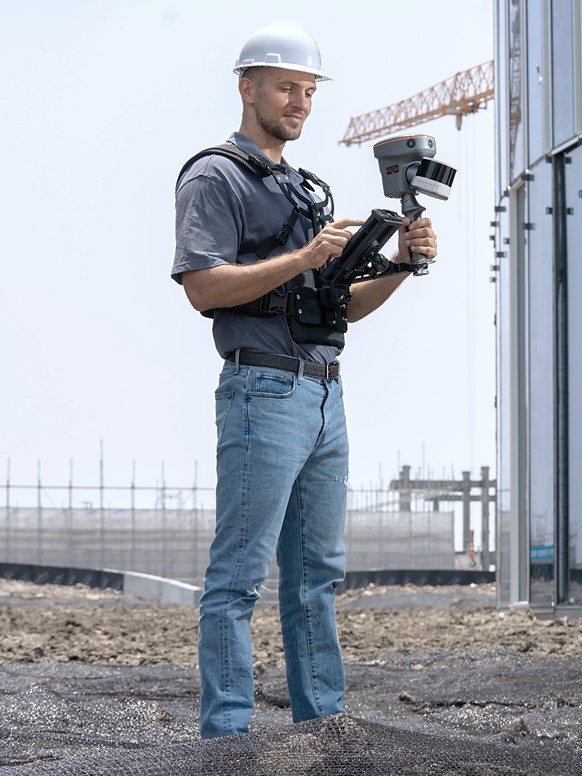
Handheld and SLAM-based scanning: A backpack or handheld scanner that uses Simultaneous Localisation and Mapping algorithms to track the sensor's own motion through a scene without external positioning. This category is what unlocked indoor scanning, basement mapping, mine inspection, and any environment where GNSS is not available. Accuracy is typically 1 to 5 cm depending on the SLAM solution and scene geometry, which is a different bracket from TLS but appropriate for the use cases.
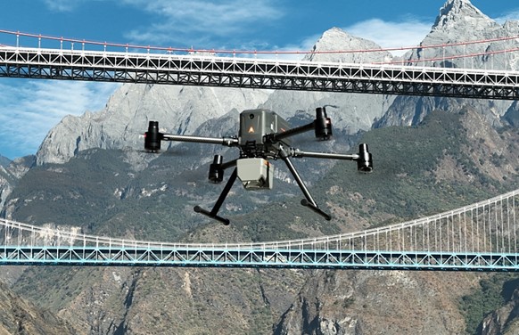
Airborne Laser Scanning (ALS): A scanner mounted on a fixed-wing aircraft, helicopter, or UAV, looking down at the terrain below. ALS is the workhorse for topographic mapping, forestry, flood modelling, and corridor surveys at landscape scale. UAV-borne ALS in particular has reshaped the small-area survey market in the last five years, with systems delivering 10 to 30 mm vertical accuracy at survey altitudes a drone can fly.
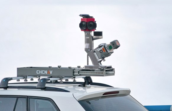
Mobile Laser Scanning (MLS): A scanner mounted on a vehicle, train, or boat, integrated with a high-precision GNSS plus inertial navigation system that georeferences every point. MLS captures kilometres of corridor (roads, rail, coastline, pipelines) in a single pass at vehicle speed. The accuracy budget is tighter because the sensor is moving, so the GNSS and IMU performance largely sets the achievable point-cloud accuracy.
Terrestrial Laser Scanning (TLS): A tripod-mounted scanner that captures dense point clouds from a fixed position. TLS is the form factor for as-built surveys of buildings, plants, and bridges, where millimetre-class accuracy and complete coverage of a known scene matter more than throughput. Range is typically 100 to 300 metres, with sub-centimetre noise at short range. The user moves the tripod between stations and registers the scans together in post-processing.
A buyer screening a LiDAR purchase usually starts by picking the form factor that matches the operational reality (mounted on a vehicle? worn on the back? flown? sat on a tripod?), then narrows by spec inside that category.
Accuracy, Range, and Wavelength Tradeoffs
Three numbers dominate LiDAR product comparisons: range, point rate, and accuracy. They are not independent; a system that pushes one usually compromises another, and understanding the tradeoffs is the difference between buying the right tool and buying a benchmark winner that does not fit the job.
Range is set by laser power, wavelength, and detector sensitivity. A 1550 nm system can run at much higher pulse energy than a 905 nm system while staying eye-safe, which translates to longer range. That is why long-range airborne LiDAR is almost always 1550 nm. The tradeoff is that 1550 nm light is absorbed by water more strongly than 905 nm, so bathymetric and shallow-water LiDAR uses different wavelengths (typically 532 nm green for water penetration). For terrestrial and mobile scanning at shorter ranges, 905 nm dominates because it is cheaper, more compact, and the range cost is acceptable.
Point rate sets how dense the cloud can be, and how fast a survey can be flown or driven. A 2 million pulses per second airborne system flying at 100 m altitude and 10 m/s ground speed delivers a hundred or more points per square metre, which is enough for most topographic and corridor work. Pushing point rate higher requires either more lasers, faster beam steering, or both, and each of those adds cost and weight. For UAV ALS the weight tradeoff is hard: a heavier sensor needs a heavier drone, which limits flight time and survey area.
Accuracy is the headline spec but the most context-dependent. A LiDAR with 5 mm linear ranging accuracy can still produce a point cloud with 5 cm absolute accuracy if the GNSS and IMU integration is weak. The reverse is also true: a moderately accurate ranger paired with a strong GNSS plus INS can deliver tighter survey results than the spec sheet suggests. For mobile and airborne scanning especially, judging a system on its ranging accuracy alone misses the point. The end-to-end accuracy budget is what matters, and that is where the navigation stack shows up.
Real-World Applications of LiDAR Technology
LiDAR is now embedded in workflows that did not exist a decade ago. The breadth of use cases is the reason the technology has become a default rather than a specialty.
Topographic and corridor mapping: Airborne LiDAR maps watersheds, road and rail corridors, and powerline networks at scale. Ground filtering algorithms produce bare-earth terrain models that feed flood modelling, infrastructure design, and engineering volumetrics.
BIM, as-built, and reality capture: Terrestrial and SLAM-based scanners generate the geometry layer for building information models, retrofit projects, and digital twins. Construction firms increasingly require LiDAR-derived as-built geometry as part of project handover.
Forestry and natural resource management: Multi-return airborne LiDAR measures canopy height, biomass, and stem density across entire forests. The data underpins carbon accounting, fire risk modelling, and harvest planning.
Autonomous vehicles and robotics: Solid-state LiDAR provides the perception layer for autonomous driving, last-mile delivery robots, and industrial AGVs, working alongside cameras and radar to detect obstacles in real time.
Mining and underground: Handheld and SLAM-based LiDAR maps tunnel networks, stockpiles, and stope geometry where GNSS is unavailable. Volumetric calculations from LiDAR scans now drive monthly reconciliation in many operations.
Heritage and archaeology: Ground-based LiDAR documents archaeological sites and historic buildings at sub-millimetre detail; airborne LiDAR with multi-return processing has revealed entire ancient cities under jungle canopy.
Each of these uses puts different stress on the accuracy, range, and form factor tradeoffs above. The best system for one is rarely the best for another.
CHC Navigation's three-platform LiDAR lineup: handheld SLAM (RS10), airborne LiDAR (AA6+X500), and multi-platform LiDAR (AU20). The combined portfolio captures high-resolution data for smart cities, infrastructure development, environmental monitoring, forestry management, mining, disaster response, construction monitoring, and asset management.
Choosing the Right LiDAR for Your Workflow
Three questions will narrow most LiDAR purchase decisions before you compare any spec sheets. First, what is the operating envelope: tripod, vehicle, drone, or backpack? That answers form factor. Second, what is the scene scale: a 10 m room, a 1 km corridor, a 100 hectare site? That answers range and point density. Third, what is the deliverable accuracy: 5 mm for as-built, 30 mm for topo, 1 to 5 cm for indoor SLAM? That answers the sensor class and the navigation integration the system needs.
Beyond those three, the practical buying decisions split between the LiDAR sensor itself and the integrated platform around it. Standalone sensors give system integrators flexibility but require in-house engineering for synchronisation, georeferencing, and software. Integrated platforms (sensor plus GNSS, IMU, controller, and processing software in one product) reduce time to first useful point cloud and are usually the right choice for surveying and engineering teams who want to operate the system rather than build it.
CHC Navigation develops LiDAR solutions across three main hardware platforms—airborne systems for UAV mapping, mobile mapping platforms for corridor applications, and handheld and backpack SLAM scanners—supported by a comprehensive software workflow that converts raw point clouds into project-ready deliverables. The full range of 3D laser scanning and reality capture products on the geospatial site lets a buyer screen by application rather than by sensor specification, and the 3D mobile mapping solution page walks through how the sensor, navigation, and software layers come together in a production workflow.
The Bigger Picture
LiDAR technology has moved from specialty instrument to default measurement layer for any project that needs three-dimensional geometry at scale. The physics has not changed, but the engineering around the physics has matured to the point where a buyer no longer has to choose between accuracy and throughput, or between range and form factor, the way they did a decade ago. What is left is the more useful question: which form factor matches the work, which accuracy class meets the deliverable, and which integrated stack gets the project to a usable point cloud fastest. Asking those three questions in the right order is what separates a successful LiDAR purchase from a sensor sitting on a shelf.
____
About CHC Navigation
CHC Navigation (CHCNAV) develops advanced mapping, navigation, and positioning solutions designed to increase productivity and efficiency. Serving industries such as geospatial, agriculture, machine control and autonomy, CHCNAV delivers innovative technologies that empower professionals and drive industry advancement. With a global presence spanning over 140 countries and a team of more than 2,200 professionals, CHC Navigation is recognized as a leader in the geospatial industry and beyond. For more information about CHC Navigation [Huace:300627.SZ], please visit: https://www.chcnav.com/about/overview
Find the Right LiDAR for Your Project
Talk with CHCNAV experts about airborne, vehicle-mounted, and handheld LiDAR systems tailored to your surveying, mapping, construction, and reality capture workflows.